- INTENDED USE
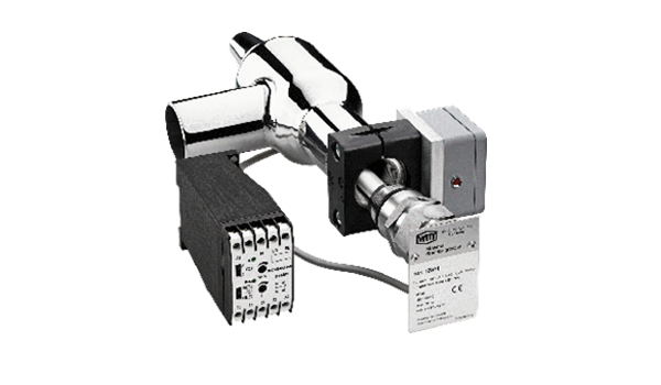
The maximum level switch NGX with TÜV design approval (certificate No. 968/EL 743.00/11) is designed to protect compressors within a refrigeration plant against liquid hammer (e.g. to conform with TRAS110). The maximum level switch is not suitable to be used as a minimum level switch or level switch. - RANGE OF OPERATION
The mechanical operated NGX can be used on surge drums and liquid receivers and is suitable for all common refrigerants with a density ρ of at least 600 kg/m³. Even when electrical level switches are installed, the use of the design-approved NGX, to switch off the compressors, is mandatory.
3. SCOPE OF DELIVERY (STANDARD)
Sensor NGX with junction box
Brackets to connect the NGX to the 1“ of the stop valve
Stop valve EA 32 – G1“-I
Relay BNRt (for installation in the switch gear, see installation instructions W 4651-6.11-)
Optional
Stop valve in stainless steel
Socket connection G 1“-NGX (when used with foreign valves)
- Detail
A) Switch
Housing material: 1.4571
Balancing bar: PTFE/
Connection: G 1“ outer thread
Pressure- / Temp.-Range: PB 25 bar / +80°C to –50°C
Weight: 0.6 kg
B) Junction box
Material: Aluminum
Dimensions: 63 x 58 x 40 mm
Protection Class: IP 65
Connections: 2 x PG 9
Weight: 0.36 kg (Junction box with brackets)
C) Brackets
Material: PP – black
Dimensions: 60 x 71 x 30 mm, hole appr. ø 42 mm
With EA 32 /G1” or EA 40/G1” valve
D) Reed-Contact
Voltage: 14 V AC/DC
Current: max. 0.5 A
Cycles: 1000 / s
Contact: Rhodium
- DESCRIPTION OF OPERATION
The switching activating point is located in the center line. Therefore the center line of the maximum level switch
determines the maximum level in the vessel that is used for the control. In the NGX housing there is a balancing
bar, which consists on one side of PTFE and on the other side there is a magnet fitted (these are the only
materials in contact with refrigerant). When the refrigerant level rises within the surge drum to the connection of
the NGX, the PTFE float will get in contact with refrigerant and start to drift up. The magnet on the other side of
the balancing bar will move downwards. A reed-contact that is installed outside of the refrigerant surrounding will
recognize the position of the magnet and will open when about 4mm are passed in the bottom position. The
signal will be transferred through the relay BR-NWt and an auxiliary contactor within the switchgear to the compressor control.
An LED display connected in series with the reed-switch is illuminated during normal operation. If the LED is not
illuminated the following reasons might occur:
The maximum level in the surge drum has been exceeded
The power supply was interrupted (cable breakage or misconnected cable)
The reed-contact is defect
The magnet has been contaminated (with metal particles).
Note: The NGX cannot be connected directly to a SPS control. (If the wiring diagram as shown on page 3 of the installation instructions of the BR-NWt W 4651-6.11 is modified, the design approval is void)


